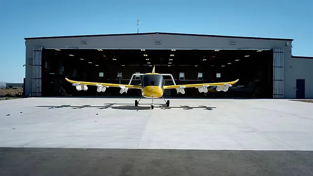
Advanced Air Mobility (AAM) comprising Unmanned Aerial Vehicles (UAVs) and Urban Air Mobility (UAM) with less than 100 nautical miles (nm) flying range is an emerging quick mode of transport in large cities with heavy traffic jams, where the possibility of using helicopters is ruled out due to dense population and annoying noise levels of these rotorcraft.
With significant advances in battery technology and electric propulsion, electric vertical takeoff and landing (eVTOL) aircraft form a critical role in UAM to offer sustainable transport of passengers and cargo loads in densely populated large cities around the world. An increase in the production and operation of eVTOL aircraft and UAVs within populated civilian areas at relatively low altitudes creates noise annoyance issues that impact human health and well-being.
Additionally, as eVTOL aircraft designs evolve, researchers are still assessing the types of noise and vibration sources and the means to control them for the comfort of the pilot and passengers on board.
The Federal Aviation Administration (FAA) in the USA and European Union Aviation Safety Agency (EASA) in the EU have formed working groups on Noise Vibration Harshness (NVH) to formulate strict noise regulations on UAM aircraft and ensure compliance by different eVTOL and UAM manufacturers on acceptable community noise levels (exterior noise) and pilot and passenger comfort levels during air travel (interior noise).
Different research facilities under the aegis of the National Aeronautics Space Administration (NASA) at Langley Research Centre in Hampton Virginia and Glenn Research Centre in Cleveland Ohio, have been assisting FAA in developing eVTOL aircraft concept designs, developing generic codes for predicting the performance and noise signatures of these aircraft, and analysing and characterising the noise generated by these vehicles.
Owing to multiple sources of noise in an eVTOL aircraft generating tonal, narrowband, and broadband noises under different flight modes of operation, efforts are being made to optimise the design for noise reduction at source, improve the lightweight fuselage design for better aerodynamics, range, and NVH, and explore active noise and vibration control technologies for improved interior noise and pilot and passenger comfort.
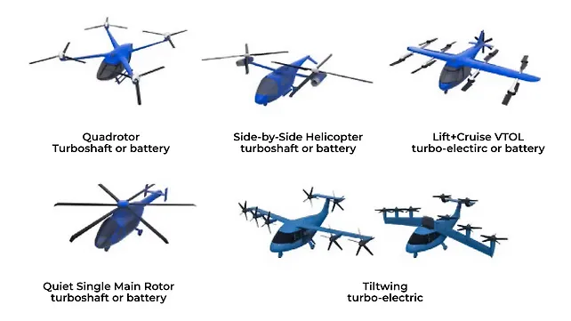
A few concepts of UEM (eVTOL aircraft) designs have been proposed by NASA [Ref 1, 2], some of which are shown in Figure 1 [Ref 1] that comprise a quadrotor aircraft, with turboshaft and electric propulsion; side-by-side aircraft, with turboshaft and electric propulsion; lift + cruise aircraft with electric and turbo-electric propulsion; a quiet single-main rotor helicopter with turboshaft and electric propulsion; and a tilt-wing aircraft with turbo-electric propulsion.
The markets and vehicle attributes identified by the NASA Emerging Aviation Markets Tiger Team include [Ref 3]:
a. Small, unmanned aircraft systems (UAS) with characteristics of, (i) no people onboard, (ii) low-mid altitude, (iii) 0-100 kts speed, (iv) 10-1,000 lbs payload, (v) 10-1,000 nm range, (vi) eVTOL/hybrid propulsion.
b. UAM with characteristics of (i) max 6 pax, (ii) piloted or remotely operated, (iii) up to 3,000 ft altitude, (iv) 0-200 kts speed, (v) 800-8,000 lbs payload, (vi) 100 nm range, (vii) eVTOL/hybrid propulsion.
c. Thin/short-haul aircraft with characteristics of (i) 9-30 pax on board, ii) up to 2 pilots, iii) up to 12.5 kft altitude, iv) 180-300 kts speed, v) 6k-30k lbs payload, vi) 200-1k nm range, vii) eCTOL
d. Large UAS and High-Altitude Long Endurance (HALE) aircraft with characteristics of (i) no people onboard, (ii) mid-high altitude, (iii) 0-250 kts speed, (iv) 100-6,000 lbs payload, (v) more than 3,000 nm range, vi) long endurance.
Keywords: eVTOL, NVH, aeroacoustics, disk loading, active noise control, active structural acoustic control, tonal noise, narrowband noise, broadband noise, BVI noise, BWI noise, rotor self-noise.
Also Read:Archer Aviation Progresses eVTOL Ambitions With Production Aircraft Unveil
eVTOL Aircraft NVH
The noise sources in a UAM (eVTOL) aircraft differ significantly from that of existing rotorcraft with aerodynamically generated noise of the rotating blades being the dominant noise source compared to the motor-generated noise, which are significantly quieter than their combustion engine counterparts.
In an eVTOL aircraft, the distributed electric propulsion (DEP), as the name indicates, comprises multiple rotors or propellers integrated across the aircraft and is enabled by the relatively low weight and high torque of the electric motors and power delivery systems. In certain eVTOL aircraft designs, the designers take advantage of the reduced weight and complexity of DEP and tile the rotors during the transition from vertical to forward flight to realise a simple mechanism for tilting the rotor nacelles or wings [Ref 3].
The eVTOL designers have been relying more on large number of smaller rotors operating at higher shaft speeds and lower torque than over fewer larger rotors operating at slower speeds because, (a) more torque is required to produce the same thrust at lower tip speeds, (b) electric motors are perfectly capable of producing torque over a wider range of shaft speeds at high efficiencies, and (c) lower blade tip speeds result in much lower aerodynamic noise – essentially taking advantage of DEP, improved motor torque-speed curve at high efficiency, and less NVH issues due to lower blade tip speeds.
Few other eVTOL manufacturers have evolved a different design for DEP using high specific torque motors (Nm/kg) and larger rotors to reduce the disk loading and hence lower power requirement during hover and vertical flight take-off/landing.
For vertical lift, it is anticipated that a larger number of rotors will be used to lift UAM vehicles rather than the one or two rotors used on conventional helicopters and tiltrotors. The rotors on a typical eVTOL aircraft may be operated with variable rotation speed, have lower tip Mach number to optimise performance and noise, and may use different onboard propulsion mechanisms for different flight operations, thus resulting in disparate rotor noise comprising markedly different frequency content and temporal character compared to a conventional rotorcraft.
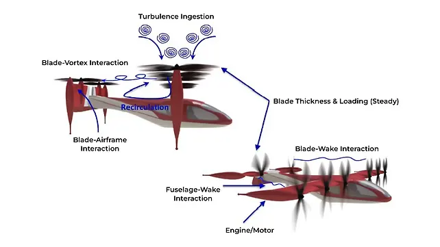
Fluid-structure interaction coupling between the rotors and airframe components in an eVTOL aircraft results in multiple noise sources and signatures. As shown in Figure 2 [Ref 3], the important noise sources include Blade-Vortex Interaction (BVI) noise, Blade-Wake Interaction (BWI) noise, Fuselage-Wake Interaction (FWI) noise, Blade-Airframe Interaction (BAI) noise, turbulence ingestion noise, and thickness, steady loading, and broadband noise.
In the case of co-axial rotors spinning in opposite directions, we also have rotor-rotor interaction noise. For rotors embedded in ducts, a design could be achieved for lower NVH with additional treatment of acoustic materials on the inside walls of the stators.
The rotating blades typically used in eVTOL lift and propulsion result in three distinct noise sources with different magnitudes and frequencies depending on the flight mode of operation — thickness, loading, and high-speed-impulsive (quadrupole) noise. The speeds of rotating blades in an eVTOL aircraft are controlled to achieve a lower tip Mach number to optimise performance and lower the high-speed impulsive noise.
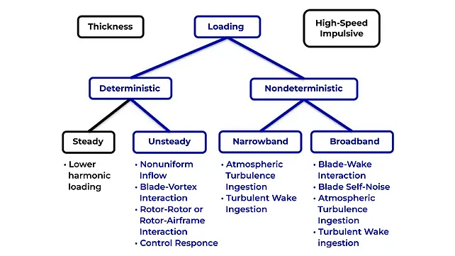
Consequently, noise due to unsteady loading arising from the closely coupled rotors and airframe components appears to be the dominant NVH issue as thickness noise is unlikely to be as high as loading noise sources. This is also confirmed by the classification of noise sources in a rotorcraft as shown in Figure 3 [Ref 4], wherein the dominant loading noise sources are marked in blue for differentiation.
As eVTOL aircraft flight operations include the transition between vertical and horizontal models of flight with complex interactions between the rotors and airframe components during a wide range of operating conditions, aerodynamic loading becomes the dominant noise source (unsteady, narrowband, and broadband) as shown in Figure 3 [Ref 4].
The dominant loading noise in an eVTOL aircraft can be broadly classified into deterministic and nondeterministic sources as seen in Figure 3 [Ref 4]. The deterministic loading is further subdivided into steady and unsteady, while the nondeterministic loading sources can be divided into narrowband and broadband noise sources.
The steady, deterministic loading is due to lower harmonic loading and is referred to as “loading noise”. Thickness noise and steady loading noise together are also known as “rotational noise” (as marked in Figure 3). The unsteady deterministic loading noise arises from a variety of unsteady loading sources including non-uniform inflow, blade-vortex interaction, rotor-rotor or rotor-airframe interactions, and unsteady response to control inputs.
Also Read:eVTOL Maker Joby Applies For UK Aircraft Certification
Nondeterministic narrowband loading noise (or narrowband random noise) is caused by the turbulence ingestion of atmospheric or turbulent wake into the rotor or propeller. The rotation of a rotor blade “chops” several times through a turbulent eddy resulting in a narrowband random noise source consisting of broad spectral peaks around the blade passage frequency (BPF) and its harmonics.
The nondeterministic broadband noise is caused by unsteady turbulent loading due to blade-wake interaction (BWI), turbulent boundary layer (TBL) causing blade-self noise, and turbulence ingestion with atmosphere and wakes.
In Figure 4, the overall sound pressure level vs blade tip Mach number is presented [Ref 3] with the assumption that the rotor has a diameter of 3 m with a solidity of 0.2 and the noise levels predicted for a “hovering” operation condition with a fixed thrust of 2,500 N. The observer is assumed to be at a distance equivalent to 10 rotor radii from the rotor hub (i.e., 15 m) in the plane of the rotor. As the tip Mach number is varied from the lower value of 0.3 (near stall) to a higher value of 0.8, the variation of the overall sound pressure levels (OASPL) and the contributions of thickness, steady loading, and broadband noise could be studied in Figure 4.
The thickness noise (blue curve) rises almost linearly and is the dominant noise for tip Mach numbers > 0.6. The steady loading noise (green curve) rises moderately for tip Mach numbers > 0.5 and has a high contribution for tip Mach numbers > 0.4. The broadband noise (red curve) raises moderately for tip Mach numbers > 0.5. The trends in thickness, loading, and broadband noise indicate that the radiated broadband noise is caused primarily due to “unsteady” surface pressure fluctuations, while the thickness and loading noises are the result of “steady” convective amplification.
Also Read:First Beta Technologies eVTOL Aircraft Lands At UPS WorldPort Hub
Also, the trend in broadband noise (red curve) indicates higher values for tip Mach number < 0.5 due to an increase in TBL noise as the angle of attack of the blade sections increases, eventually leading to flow separation. The essential takeaway from Figure 4 is that there is an “optimal” tip speed for a given rotor geometry, below which additional tip speed reductions will be ineffective in reducing noise or will even increase it.
At this “optimal” tip speed, both deterministic and nondeterministic unsteady loading noise sources will dominate. Many eVTOL rotor designs have evolved to operate near the “optimal” point, at tip Mach numbers at or below 0.5, to achieve lower noise, which is found suitable in lightly loaded condition such as the cruise mode of operation. Hence, the critical aspect of achieving low NVH during eVTOL operations is to mitigate the unsteady loading noise sources (showcased in blue in Figure 3) operating at optimal tip Mach number.
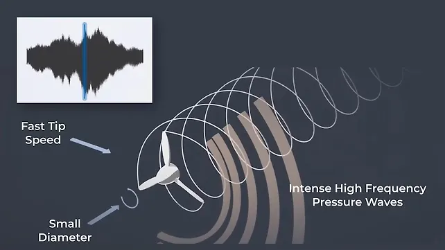
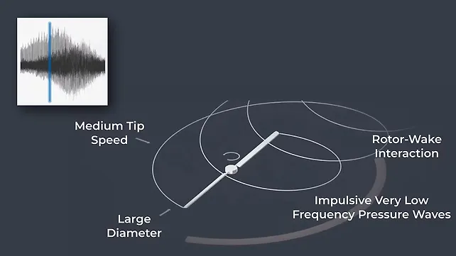
In Figures 5 through 7, the noise signatures and representative pressure wave propagations are captured for a piston propeller aircraft, a helicopter, and an eVTOL aircraft, respectively [Ref 5]. In Figure 5 for piston propeller aircraft, the rotors have small diameters and fast tip speeds, leading to intense high-frequency pressure waves. The helicopter noise signature in Figure 6 is characterised by large diameter, medium tip speed, impulsive very low-frequency pressure waves, and rotor-wake interactions.
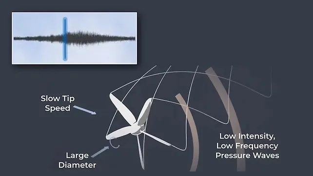
The eVTOL aircraft noise signature in Figure 7 is a result of large blade diameter, slow tip speed, and low-intensity low frequency pressure waves and is an order of magnitude lower than the noise signatures in Figures 5 and 6. The pressure waves in Figure 6 clearly indicate that BVI is the most significant source of aerodynamic interaction noise in a helicopter and is generated by the interaction between the rotor and its own wake.
The aerodynamic noise in an eVTOL aircraft as depicted in Figure 7 becomes more pronounced during descending and manoeuvring flight, when a rapid fluctuation of aerodynamic loads is experienced from the rotor blades passing near the tip vortices formed by preceding blades, resulting in the radiation of highly impulsive noise.
Noise Standards for UAM
With increased urbanisation, residents living in large cities and towns continuously experience vehicular pollution from traffic snarls and annoying noise from vehicle driving and honking. Upon UAM becoming a reality in the near future with a large number of eVTOL aircraft plying in dense neighbourhoods, residents may be subject to additional annoyance from UAM noise pollution, necessitating a hybrid noise standard addressing both ground and upper space noises.
Numerous studies carried out over the past few decades clearly confirmed that considerable noise damage is caused by traditional aircraft supplemented by the fear and fright of residents living near airports. Regulatory authorities ought to formulate stricter noise standards for the successful deployment of UAM in urban spaces.
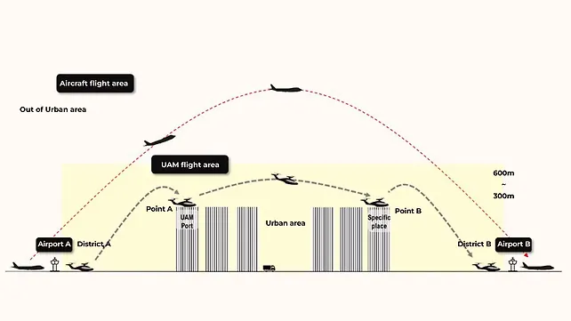
As shown in Figure 8 [Ref 6], UAM vehicles fly over the upper spaces of cities in the range of 300 to 600 m that can be blocked by buildings, the tallest of which is Burj Khalifa at 828 m. Hence, it is inappropriate to introduce and use aircraft noise standards tailored to open airports for UAM noise standards.
The noise level of commercial aircraft complies with the effective perceived noise in decibels – EPNdB-20 (Stage 2) standard established in 1960, with the aim of reducing it to the EPNdB-30 (Stage 5) level by 2030. Commercial aircraft manufacturers and airports are continuously developing noise-reduction technologies to ensure compliance with the EPNdB-30 standard.
In the case of UAM, as the noise standards are still evolving due to a lack of flight data within the city, the FAA announced guidelines in 2022 on how to build a UAM vertiport, the basic infrastructure of UAM, and formed UAM Noise Working Groups to develop the noise standards. In a joint effort, FAA and NASA have been working with the eVTOL aircraft manufacturers to build concept prototypes and encourage participation in UAM to establish the necessary certification support for UAM commercialisation and operation.
In the EU, EASA is taking a similar approach by (a) working on regulations on UAM vertiport operations and pilot licenses, (b) proposing VTOL and airframe standards and preparing regulations related to pilot certification, and (c) evolving plans to approve the use of UAM for small cargo transportation, such as courier services paving the way for commercialising UAM passenger transportation.
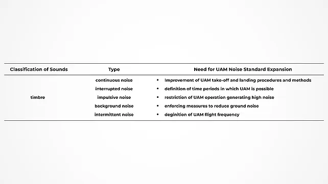
UAM noise standards account for and regulate only the loudness and pitch of a sound, comprising three elements: loudness, pitch, and timbre. The current proposal on noise standards for UAM recommends the usage of the EPNdB index, which is a combination of loudness (dB) and pitch (Hz).
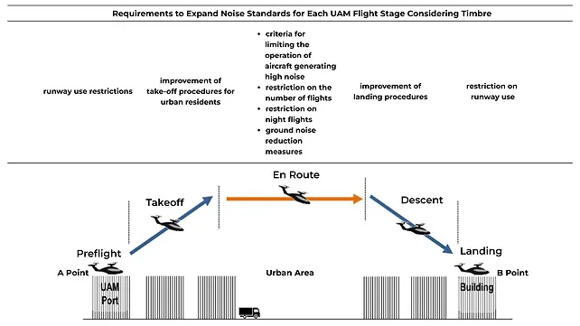
As of date, there are no regulatory standards for sensory properties related to timbre. It is highly recommended that the noise standards for UAM be expanded to include timbre also, as shown in Figure 9 [Ref 6]. Accordingly, the requirements to expand noise standards for each UAM flight stage considering timbre are captured in Figure 10 [Ref 6].
Noise & Vibration Control in eVTOL Aircraft
For better NVH in UAM aircraft, multiple approaches could be taken including, (a) Source noise reduction technologies, (b) aircraft design, (c) low-noise aircraft operations, and (d) active control.
Source Noise Reduction Technologies
The design configuration of an eVTOL aircraft decides the noise source mitigation strategies for that design. Typically, blade geometry, blade tip Mach number, number of blades per rotor, and rotor spacing define the source noise signature. While the increase of blade thickness may facilitate better propulsion, thickness noise also increases accordingly, with a 6 dB increase for doubling of thickness.
The tonal and broadband components of loading noise are impacted by surface pressure (loading) the rate of change of surface pressure, and the speed (Mach number) with higher noise levels for higher mean surface pressure and a higher rate of change of surface pressure (loading).
Source noise reduction strategies for UAM include [Ref 3]:
a. For isolated rotors and propellers:
- Increasing the number of blades;
- Optimising the blade aerofoil shape;
- Optimising the blade platform shape;
- Reducing the speed for lower tip Mach number;
- Smoother design of leading and trailing edges to prevent wakes and turbulence.
b. For rotor-airframe interactional noise effects:
- Increasing the rotor/airframe separation distances;
- Preferably placing the rotors above the airframe supports;
- Avoiding close proximity of pusher propeller configurations to a fuselage, rotor wake, or wing wake.
c. For rotor-rotor interactional noise effects:
- Adjusting the rotor blade rotational speed or phase relative to other rotors;
- Adjusting the relative rotation direction between rotors;
- Maintaining appropriate inter-rotor distance.
d. Sound barrier and sound absorptive treatments with refraction, reflection, and absorption of acoustic waves.
Aircraft Design
For aircraft design that produces optimal NVH, it is important to integrate the multi-disciplinary design, analysis, and optimisation of aircraft with the system noise prediction tools so that correct trends due to configuration changes could be established early in design with faster turnaround time.
Additionally, the design trends due to configuration changes and the influence of specific noise sources on overall NVH help understand the “sensitivity analysis” and build a decision matrix that considers different trade-offs. Design methods such as gradient-based optimisation and finite difference methods help determine the sensitivities of overall noise level to different design variables.
Alternatively, surrogate models that may help set the design direction based on sensitivity analysis could be used for “quick” design direction, though these surrogate models still need test data or other computational models along with the challenge of accurately modelling aeroacoustics using these surrogate models.
Low-Noise Aircraft Operations
The low-noise aircraft operations include operational planning and trajectory optimisation. For rotorcraft, it is suggested during take-off to depart at a high rate of climb and maintain a high altitude during the cruise to maximise propagation distances. During approach and landing, more than 6 dB of noise reductions are found to be achieved by suitably tailoring deceleration and flight path angles.
Active Control Technologies for Noise & Vibration
eVTOL aircraft noise levels have benefited from continuous enhancements in technologies enabling noise reduction at source (motors, engines, propulsors, etc.). Owing to stringent weight targets and from the perspective of safety (high crashworthiness standards) and aesthetics (stylish with excellent fit and finish), aircraft cabins and associated components use strong, lightweight, and flame-retardant composite fibre materials, resulting in unsteady rotor-airframe interaction noise (Figure 3, [Ref 4]) becoming a major noise source and posing a challenge in addressing cabin interior noise levels and sound quality.
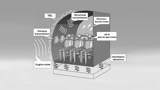
A schematic of typical noise and vibration sources and their propagation paths into an aircraft cabin is shown in Figure 11 [Ref 7]. The noise sources include TBL noise and propulsion-system-induced engine/ motor noise on the outer surface of the cabin. The vibration transmission is through the mounting points while noise transmission paths include window transmission, structure-borne transmission, and airborne transmission.
Akin to automotive interior noise control, traditional “passive” noise control measures such as the use of structural damping, insulating blankets, acoustic absorption, rubber isolation of vibrating parts, etc. would still be applicable for eVTOL interior noise control but with strict design constraints on weight and payload capacity.
Active control such as Active Noise Control (ANC) or Active Structural Acoustic Control (ASAC) will be more useful in eVTOL aircraft as the traditional passive control approaches using sound insulators and absorbers may not be effective against low-frequency noise and also add significant weight to the aircraft.
Active Noise Control (ANC)
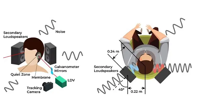
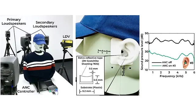
The schematic of a potential setup to achieve ANC in an aircraft is shown in Figure 12 [Ref 8], wherein each of the secondary loudspeakers generates anti-noise signals to create a “zone of quiet” with more than 10 dB of noise reduction in each ear with the size of the zone being about 1/10th of the wavelength of the sound in a diffuse sound field.
The required error signal is determined from a Laser Doppler Vibrometer (LDV) measurement of the vibration of a small membrane pick-up located close to the ear canal. The user movement is tracked by a camera that actively controls the galvanometer-driven mirrors to steer the laser beam and maintain its position on the membrane.
An experimental setup of ANC in an aircraft using feed-forward control based on a filtered-x least mean square (LMS) algorithm is shown in Figure 13 [Ref 8]. Numerous studies are carried out in [Ref 8 ] with different positions of the head, changes in LDV signal, different locations of the secondary speakers, etc to ensure the robustness of the ANC performance. A representative sound pressure level (dB) difference with ANC off and on with the reflective membrane placed near the ear canal is shown in Figure 13 with significant noise reduction across the frequency band.
ASAC using Piezoelectric Actuators and Sensors
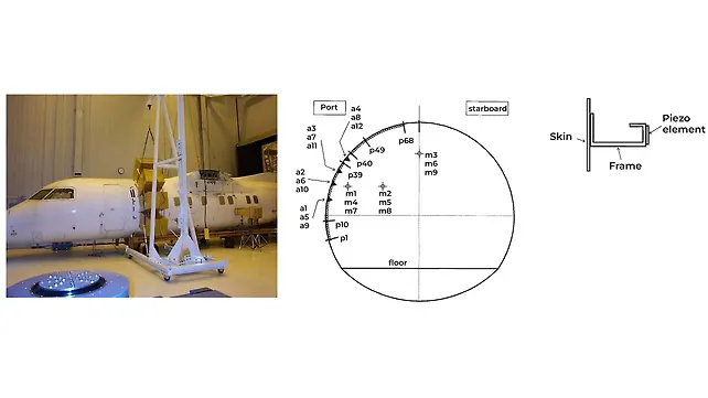
An application of ASAC using piezoelectric actuators and sensors is shown in Figure 14 [Ref 9, 10]), wherein a total of 199 piezoelectric elements (1” by 1” by ¼”) were bonded onto the fuselage frame caps with a distance of 1/8” between neighbouring piezoelectric elements formed into three large groups of actuators. The disturbance signal was generated using speaker-ring systems shown in Figure 14 (a) to simulate the propeller noise operating at 910 rpm generating a Blade Passage Frequency (BPF) of 61 Hz. A feed-forward control using a filtered-x LMS algorithm was applied using accelerometers as error sensors as shown in Figure 14 (b).
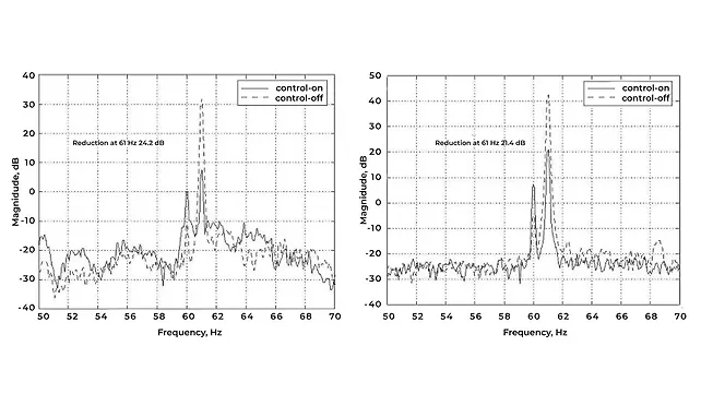
The acceleration spectra measured at accelerometer 3 and noise spectra measured at row 1 aisle seat are shown in Figure 15 (a) and 15 (b), respectively with > 20 dB reduction achieved in both cases for 900 rpm, 61 HZ BPF, showing the effectiveness of ASAC for interior noise control.
ASAC using Smart Foam Elements
Another application of ASAC involves using smart foam actuators for aircraft interior noise control that offers the benefits of both passive and active (aka hybrid) control [Ref 11]. Smart foam actuators comprising a sound-absorbing foam with an embedded distributed piezoelectric polyvinylidene difluoride (PVDF) layer designed to operate over a broad range of frequencies are affixed to the surface of the aircraft.
While the acoustic foam acts as a passive absorber and targets high-frequency noise sources, the PVDF serves as the active component and is activated to provide secondary noise signals at low frequencies to cancel the primary noise sources. An ANC methodology based on adaptive feed-forward filtered-x Least-Mean-Squared (LMS) control algorithm is used to drive the smart foam actuators affixed at different locations on the skin of the aircraft to reduce the sound pressure levels at an array of microphones using accelerometers
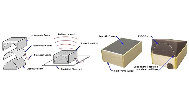
on the panel as the reference signal for the feed-forward algorithm. The smart foam details and mounting on a structure are shown in Figure 16, while a schematic of smart foam treatment in the aircraft and evaluation in a test facility is shown in Figure 17 [Ref 11].
As shown in Figure 16, the acoustic foam is shaped to hold the PVDF in the form of a half-cylinder and each side of the PVDF is affixed to the foam using a light application of spray glue. To improve the radiation efficiency of the smart foam element and thus increased volume velocity and radiated sound pressure level, each end of the PVDF film is glued to a balsa anchor that ran the full width of the smart foam element, thus creating fixed boundary conditions (Figure 16, [Ref 11]).
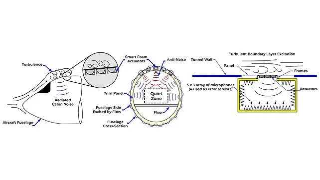
A schematic of smart foam treatment in an aircraft and evaluation in a test facility is shown in Figure 17 [Ref 11], which depicts the excitation of exterior fuselage panels by, (a) aerodynamic and turbulent boundary flow, (b) engine/ propulsion, and (c) propulsor/ wake interaction, resulting in noise radiation into the aircraft cabin.
An array of smart foam actuators is affixed between the fuselage skin and interior trim panel of the aircraft, which can be activated and controlled to act as secondary noise sources to cancel the primary noise radiation into the aircraft cabin. Similar to the schematic shown in Figure 12 [Ref 8], the schematic in Figure 17 [Ref 11] also uses a multi-channel filtered-x LMS feed-forward control algorithm and produces a “zone of quiet” with more than 10 dB noise reduction inside the aircraft cabin.
In the Mach 0.2 NASA Langley Research Center (LaRC) wind tunnel test facility shown in Figure 17, the aircraft interior is modelled using an anechoic chamber comprising a 5X3 array of microphones (with 4 error microphones) enabled by four control channels consisting of six smart foam actuators mounted to a single section of the six-bay panel and excited by the wind tunnel flow.
In Figure 18 [Ref 11], sound pressure levels are shown in the as-is situation, with passive control (effect of only foam), and with hybrid control (active + passive) using smart foam actuators. As can be seen from the figure, passive control (green curve) is effective only in the mid to high-frequency range (> 500 Hz) while the hybrid control (blue curve) is effective across the entire frequency range with significant noise reduction of peaks around 185 Hz and 640 Hz, resulting in about 6 dBA attenuation in 400-1000 Hz frequency range, as shown in the 1/3rd octave band results.
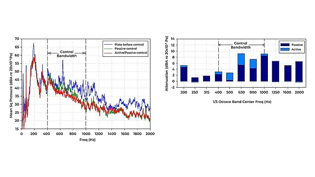
The noise reduction trends in Figure 18 confirm that smart foam actuators utilise passive material characteristics of the foam to realise, (a) noise attenuation through energy dissipation of higher frequencies in the sound absorber, and (b) vibration attenuation through energy dissipation at lower frequencies in the form of damping of panels on which the foam elements are affixed. This is clearly observed by comparing the blue and green curves, (a) at the 186 Hz peak, where energy dissipation is due to panel damping, and (b) at 640 Hz, where energy dissipation is due to sound absorption.
Conclusion
A few concept vehicles for UAM have been presented along with potential markets and vehicle attributes by the NASA Emerging Aviation Markets Tiger Team. Different kinds of noise sources in a typical eVTOL aircraft are presented including tonal, narrowband, and broadband. Classification of noise sources in rotorcraft is presented in terms of thickness, loading, and high-speed impulsive noise sources with unsteady loading dominating the noise of these aircraft.
The variation of overall sound pressure level (OASPL) vs Tip Mach Number is presented along with the details of thickness, loading, and broadband noise variations and the need for an optimal tip Mach number to balance performance and NVH. A comparison of noise spectrums and Pressure Wave Propagation is done for a piston propeller aircraft, a helicopter, and eVTOL aircraft and shows how BVI is the most significant source of aerodynamic interaction noise, especially for propeller aircraft and helicopters.
Noise standards for UAM are presented briefly with suggestions on the expansion of UAM noise standards considering timbre as an important element of sound along with the requirements to expand noise standards for each UAM flight stage. For improved NVH in eVTOL aircraft, design directions on noise source reduction technologies, better aircraft design, and low-noise aircraft operations are presented followed by recent developments in active control technologies of sound and vibration in terms of ANC and ASAC using piezoelectric actuators and sensors and smart foam elements using accelerometers and microphones as error sensors.
In both ANC and ASAC, a zone of quiet with more than 10 dB noise reduction could be achieved for improved NVH in the aircraft cabin. In the case of smart foam actuators, energy dissipation is observed through damping in the lower frequencies and through sound absorption at higher frequencies.
Future Work
For UAM to be successful in densely populated urban areas, ultra-quiet aircraft operations are a must that could be achieved using a strong multidisciplinary research effort combining research in aerodynamics, acoustics, numerical methods, active controls, advanced materials, low-noise flight operations, and autonomous flying capabilities, to name a few.
It is observed that unsteady loading will dominate the noise of these aircraft. Depending on the design configuration of an eVTOL aircraft (rotors, fixed vs tilt wing, etc.), strong aerodynamic interactions between the lifting and propulsion components and the airframe occur, resulting in annoying noise signatures.
Only recently, aero-acousticians have started understanding the complex interactions between rotors or propellers and turbulent wakes generated by upstream aerodynamic components in eVTOL aircraft, while enough research has been carried out over many decades on blade-vortex interaction noise, blade-wake interaction noise, and rotor-airframe interaction noise for propeller aircraft and rotorcraft such as helicopters.
A multidisciplinary approach is required to accurately build UAM noise source models using computational aeroacoustics by building on the prior research regarding helicopter BWI and propeller turbulence ingestion noise. A hybrid noise standard for UAM that includes the timber element of sound and that incorporates the noise standards from the automotive industry may be required to address the noises experienced by urban residents from both on-road vehicles and low-flying eVTOL aircraft. Further research needs to be carried out on active control technologies for cost-effective and scalable solutions to address NVH issues in eVTOL aircraft.
References
[1] Johnson, W., and Silva, C. “NASA concept vehicles and the engineering of advanced air mobility aircraft,” The Aeronautical Journal (2022), 126, pp. 59–91 doi:10.1017/aer.2021.92
[2] Silva, C. et. al, “VTOL Urban Air Mobility Concept Vehicles for technology development,” AIAA Aviation Forum, 2018 Aviation Technology Integration, and Operations Conference, AIAA 2018-3847, June 25-29, 2018, Atlanta, Georgia, https://doi.org/10.2514/6.2018-3847
[3] Rizzi, S.A. et. al, “Urban Air Mobility Noise: Current Practice, Gaps, and Recommendations,” October 2020, NASA/TP–2020-5007433, https://ntrs.nasa.gov/api/citations/20205007433/downloads/NASA-TP-2020-5007433.pdf
[4] Greenwood, E. et. al, “Challenges and opportunities for low noise electric aircraft,” International Journal of Aeroacoustics 2022, Vol. 21(5-7) 315–381, https://doi:10.1177/1475472X221107377
[5] Joby Aviation, “How quiet is the Joby aircraft during flyover?” https://www.youtube.com/watch?v=itP8-3j2UZI
[6] Kim, J.H. “Urban Air Mobility Noise: Further Considerations on Indoor Space,” International Journal of Environmental Research and Public Health, 2022, 19, 11298, https://doi.org/10.3390/ ijerph191811298
[7] Dimino, I. and Aliabadi, F., ”Active Control of Aircraft Cabin Noise,” September 2015, https://doi.org/10.1142/p996
[8] Xiao, T. et. al, “Ultra-broadband local active noise control with remote acoustic sensing,” Nature Scientific Reports, (2020) 10:20784, https://doi.org/10.1038/s41598-020-77614-w
[9] Zimcik, D. G. “Active control of aircraft interior noise,” RTO AVT Symposium on Habitability of Combat and Transport Vehicles: Noise, Vibration and Motion, Prague, Czech Republic, 4-7 Oct. 2004
[10] Grewal, A. et. al, “Active cabin noise and vibration control for turboprop aircraft using multiple piezoelectric actuators,” Journal of Intelligent Material Systems and Structures, vol. 11, June 2000, pp. 438-447, doi:10.1177/104538900772664602
[11] Griffin, J.R., “The control of interior cabin noise due to a turbulent boundary layer noise excitation using smart foam elements,” M.S. Thesis, Virginia Tech (VPI&SU), October 2006, https://vtechworks.lib.vt.edu/bitstream/handle/10919/32804/SmartFoamETD.pdf?sequence=1
About the Author: Dr Arunkumar M Sampath works as a Principal Consultant in Tata Consultancy Services (TCS) in Chennai. His interests include Hybrid and Electric Vehicles, Connected and Autonomous Vehicles, 5G/6G, Cybersecurity, Functional Safety, Advanced Air Mobility (AAM), AI, ML, Data Analytics, and Data Monetization Strategies.
Also Read:
United Airlines Makes Pre-Delivery Payment For 100 eVTOL Aircraft
Supernal, Electric Power Systems To Advance eVTOL Battery Capabilities